12 Steps for Designing SMPS Transformers
Designing magnetic components for SMPS can be challenging due to the increasing demands of modern electronics designs.
Following these 12 steps can help engineers navigate the challenges and ensure a successful project.
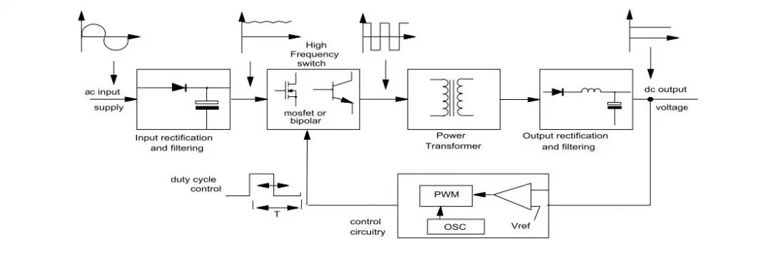
Power Supply, SMPS, Switched-Mode
The following parameters are essential for designing SMPS magnetic components:
- Input voltage range
- Output voltage
- Output power or output current
- Switching frequency
- Operating mode
- Maximum duty cycle of the IC
- Safety requirements
- Ambient temperature
- Size requirements
Step 1: Core Choice
Make your preliminary core choice based upon the power requirements of the application, the switching topology, and the frequency.
Ferrite cores are the best choice for high-frequency applications.
For operation below 500 KHz, most designers will use a core material with a permeability of 2000 to 2500.
Permeability varies significantly with temperature rise and operating flux density.
In general, this will not affect operation of the converter as long as the core is not close to saturation as the inductance (which controls the mode of operation) is primarily determined by the air gap.
However, temperature rise, and operating flux density will affect core losses, and this must be taken into account to ensure reliable operation.
Core Shape
The core shape and window configuration are important for high-frequency transformer design to minimize losses. The winding window area should be as wide as possible to maximize winding breadth and minimize the number of layers. This minimizes AC winding resistance.
- EFD and EPC cores are used when a low profile is required.
- EE and EF are good choices and generally used with either vertical or horizontal bobbins (vertical bobbins are good when footprint space is at a premium).
- ETD and EER cores are usually larger, but have a wide winding area, which makes them particularly good for higher power designs and multiple output designs.
- PQ cores are more expensive but take up slightly less PC board space and require less turns than E cores.
- Larger core size will be needed for a margin wound type transformer than for a triple insulated type to allow room for the margins.
Core Size
There are many variables involved in estimating the appropriate core size.
- One way to select the proper core is to refer to the manufacture’s core selection guide.
- The core area product (WaAc), obtained by multiplying the core cross-section area by window area available for winding is widely used for an initial estimate of core size for a given application.
- Core Power handling capability does not scale linearly with area product or core volume. A larger transformer must operate at a lower power density because the surface area dissipating heat does not increase in proportion to the volume producing the heat.
The table below gives an overview of core types as a function of power throughput:
| Output power level (watts) | Recommended core types |
| 0–10 | EFD15, EF16, EE19, EFD20, EFD25 |
| 10–20 | EE19, EFD20, EF20, EI22, EFD25 |
| 20–30 | EI25, EFD25, EFD30, ETD29, EER28(L) |
| 30–50 | EI28, EER28(L), ETD29, EFD30, EER35 |
| 50–70 | EER28L, ETD34, EER35, ETD39 |
| 70–100 | ETD34, EER35, ETD39, EER40 |
| 100–150 | EI50, EE40, EER42 |
| 150–200 | EI60, EE50, EE60, EER49 |
| 200–500 | ETD44, ETD49, E55 |
| > 500 | ETD59, E65, E70, E80 |

The WaAc / power output relationship is obtained by:

Kf = Form factor; for square wave Kf = 4
Ku = Window utilization factor
J = Current density
Bmax = Operating flux density
F = Switching frequency
Po = Output power
Step 2: Volt-Time Product (V-µSec) Value
Determine the V-T value based upon the maximum allowable duty cycle and the frequency.

Step 3: Primary Turns
Determine the minimum number of primary turns required to support the worst case V-T value.

Note : B < 0.3T for ferrite
Step 4: Turns Ratio
Calculate the secondary/primary turns ratio.
Isolated Topology Secondary / Primary Turns Ratio
Flyback 
Forward 
Push-Pull 
Half-Bridge 
Full-Bridge 
Note: Diode drop Vd = 0.5-1V
Step 5: Secondary Turns
Choose the exact primary and secondary turn counts to be used based upon the Np and Ns/Np.
Step 6: Primary Inductance
Calculate the required primary inductance:

The table below shows typical efficiency figures:
| Topology | Efficiency Range (η) |
| Flyback | > 70% |
| Forward | > 85% |
| Push-Pull | > 90% |
| Half-Bridge | > 90% |
| Full-Bridge | > 90% |
Step 7: Air Gap
The smallest size and lowest cost transformer is achieved by fully utilizing the core. In a specific application, optimum core utilization is associated with a specific optimum core gap length.
The core gap will be determined by the number of primary turns and the inductance specification. The designer will verify that the gap is sufficient to prevent core saturation.
AL = L / NP²

Note: Push-pull, forward, half-bridge, and full bridge converter topologies typically do not require an air gap, since it is actually true transformer action.
Step 8: Wire Size
Once all the winding turns are determined, the wire size should be properly chosen to minimize the winding conduction loss and leakage inductance. The winding loss depends on the RMS current value, the length and the width of wire, also the transformer structure.
- The wire size could be determined by the RMS current of the winding.
- Winding loss is a function of the amount of resistance in the wire.
- The resistance is composed of DC resistance and AC Resistance. At low frequencies, RDC >> RAC, RAC can effectively be ignored.
- At high frequencies, it may be necessary to use stranded/Litz wire or foil to minimize AC resistance.
- Due to the skin effect and proximity effect of the conductor, the diameter of the wire/strand should be less than 2*Δd (Δd = skin effect depth)
- Assume current density is typically 3–6 A/mm².
Step 9: Fill Factor
The fill factor means the winding area to the whole window area of the core (should be < 1). For initial designs, it is recommended that a fill factor no greater than about 50% to be used. For transformers of high power density and multiple outputs, this factor may need to be reduced further.
- After the wire sizes have been determined, it is necessary to check whether the window area with the selected core can accommodate the windings calculated. The window area required by each winding should be calculated respectively and added together, the area for inter-winding insulation, bobbin, and spaces existing between the turns should also be taken into consideration.
- Based on these considerations, the total required window area is then compared to the available window area of a selected core. If the required window area is larger than the selected one, either the wire size must be reduced, or a larger core must be chosen. Of course, reduction in wire size increases the copper loss of the transformer.
Step 10: Core Loss
In a transformer, core loss is a function of the voltage applied across the primary winding. In an inductor, it is a function of the varying current applied through the inductor. In either case, the operating flux density level needs to be determined to estimate the core loss. With the frequency and B level known, core loss can be estimated from the material core loss curves.
Step 11: Copper Loss
In a transformer, copper loss is a function of AC and DC resistances.
Step 12: Temperature Rise
Temperature rise is important for overall circuit reliability. Staying below a given temperature ensures that wire insulation is valid, that nearby active components do not go beyond their rated temperature, and overall temperature requirements are met. Thermal runaway can occur causing the core to heat up to its Curie temperature resulting in a loss of all magnetic properties and catastrophic failure. Total loss is measured in watts and surface area is in cm².

Transformer Construction
Transformer construction has a large effect on the leakage inductance of the primary winding. Leakage inductance leads to a voltage spike at turn off of the semiconductor switch, so minimizing the leakage inductance will result in a lower voltage spike and lower or even no requirement for the snubber circuit on the primary.
The following techniques are used to minimize leakage inductance:
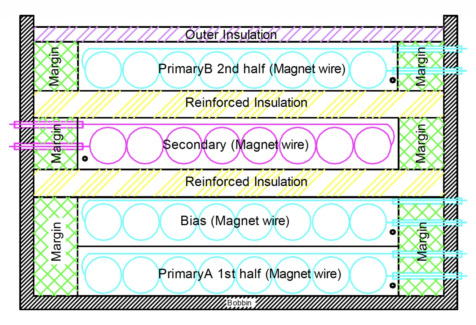
- Transformer windings should always be concentric i.e. on top of each other to maximize the coupling, for this reason, split and multi-section bobbins should not be used.
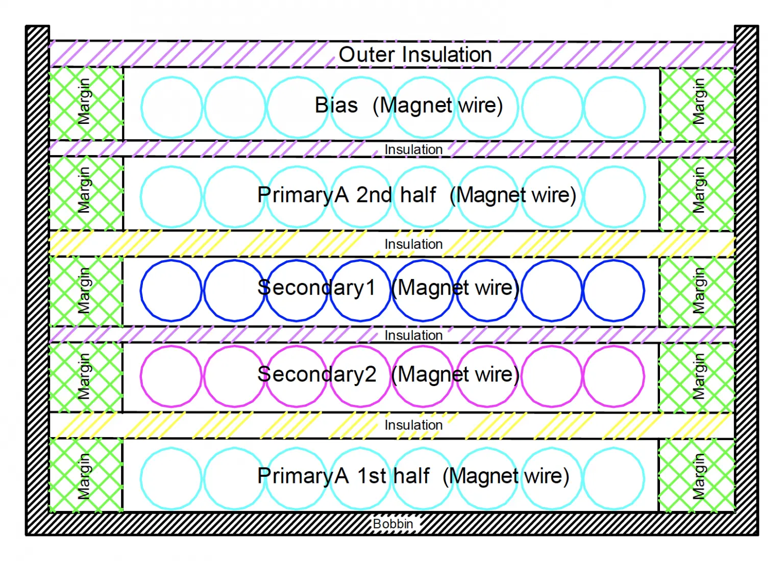
- Use of a split primary winding, where the first layer of the winding is the inner-most winding and the second layer is wound on the outside.
- In a multiple output transformer, the secondary with the highest output power should be placed closest to the primary for the best coupling and lowest leakage.
- Secondary windings with only a few turns should be spaced across the width of the bobbin window instead of being bunched together in order to maximize coupling to the primary. Using multiple parallel strands of wire is an additional technique of increasing the fill factor and coupling of a winding with few turns
- To minimize leakage inductance and still meet isolation requirements, design the windings using triple insulated wires and minimal tape layers.
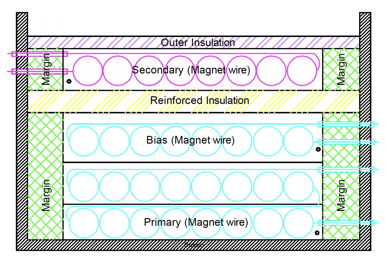
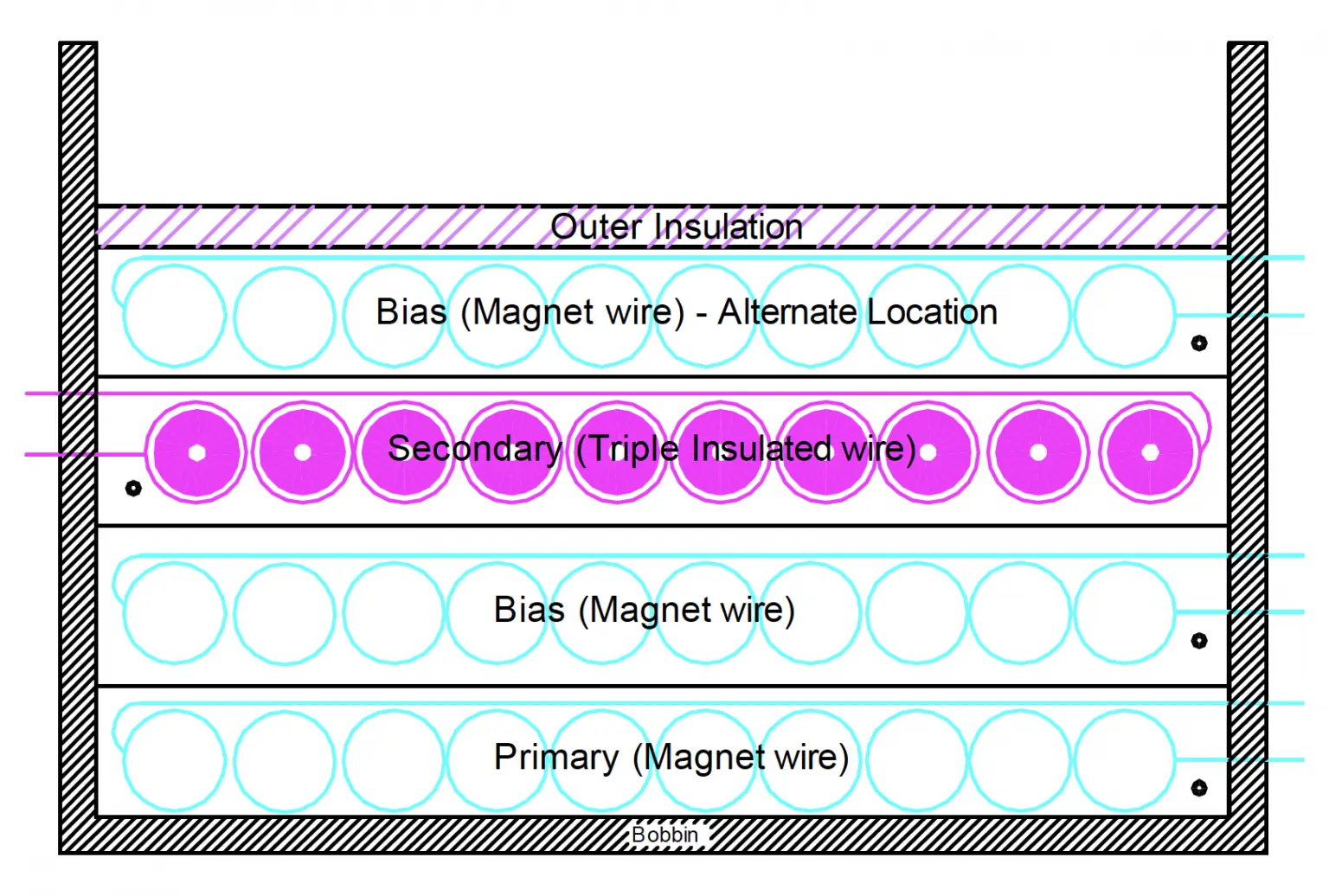
Margin wound construction or triple insulated wire construction is used to meet international safety standards.
Transformer shielding
Using a flux band (copper shield) around the entire transformer will provide a circumferential radiation shield for the eddy currents in the transformer. This shield is simply a grounded loop of copper foil around the entire assembly. Use of this technique requires careful consideration of isolation requirements and creepage and clearance issues.
Vacuum Impregnation
High-performance applications such as military, aerospace, medical, and high voltage often require an extra level of protection and isolation. Vacuum impregnation with epoxies and/or varnishes can ensure this high level of performance and endurance.
Let's work together!
Whether you have an existing specification or you are at the beginning of the design process, we are here to help.

